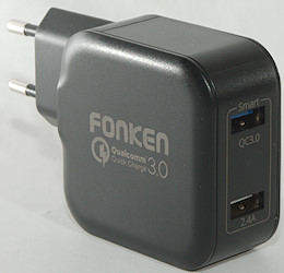
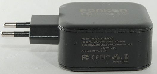
Fonken dual USB charger QC3 TPA-53120125VU01
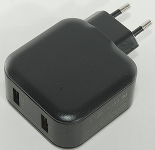
Official specifications:
- Dual USB Port
- With LED lamp
- Quick charge 3.0 Technology
- Up to 27W output
- Fast charge more than the Ordinary charger
- Multiple security protection
- Smart IC Automatic switching ensures maximum output power
I got it from a Aliexpress dealer: FONKEN Store

It was in a brown cardboard box with the Fonken name on it.
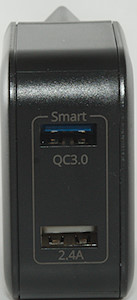
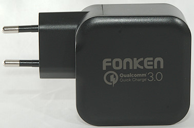
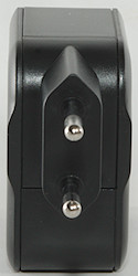
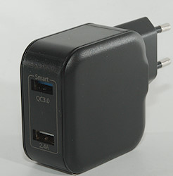
There is a blue led inside the charger that can be seen through empty usb connectors.
Measurements
- Std. usb output is auto code with DCP, Samsung, Apple 2.4A
- QC3 usb output is DCP, QC3, PE2.0
- Power consumption when idle is 0.14 watt
- Minimum QC3 voltage is 3.8 volt.
- The two outputs are independent
- There is a led behind each usb output.
- Weight: 91g
- Size: 95.3 x 58.3 x 29.8mm
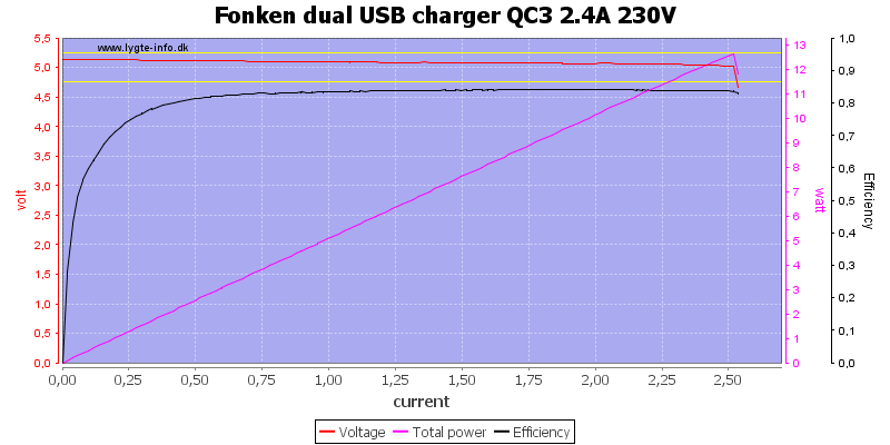
The 2.4A output can deliver 2.5A, this is fine.
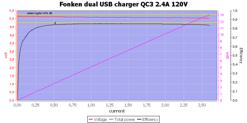
And about the same at 120VAC.
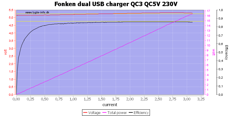
QC output is rated for 3A and can deliver slightly above 3A. Output increases with load, this means it has cable compensation.
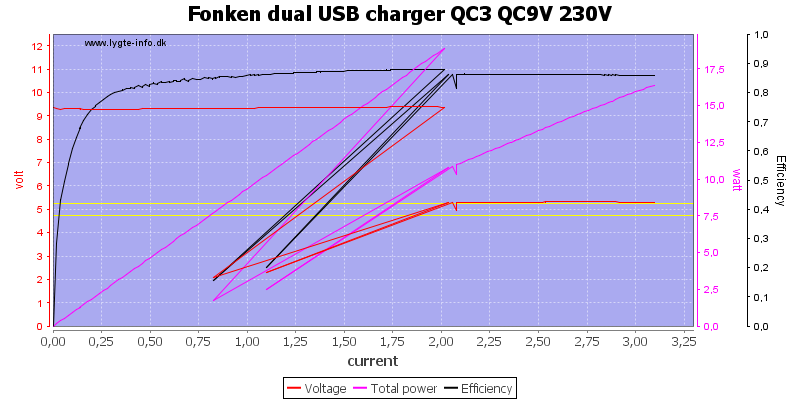
AT 9V it is rated for 1.67A and can deliver 2A.
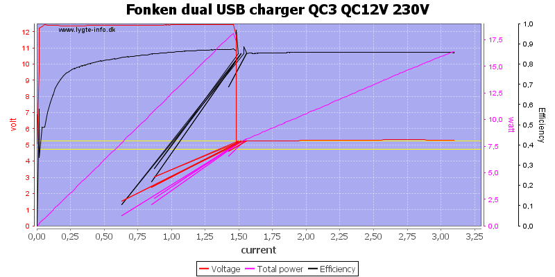
12V is rated 1.25A and can deliver 1.5A
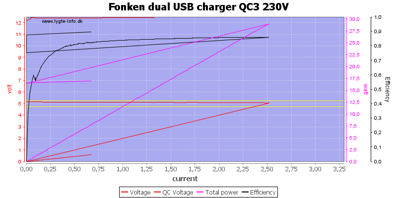
Running both outputs up to a bit above rated current worked fine.
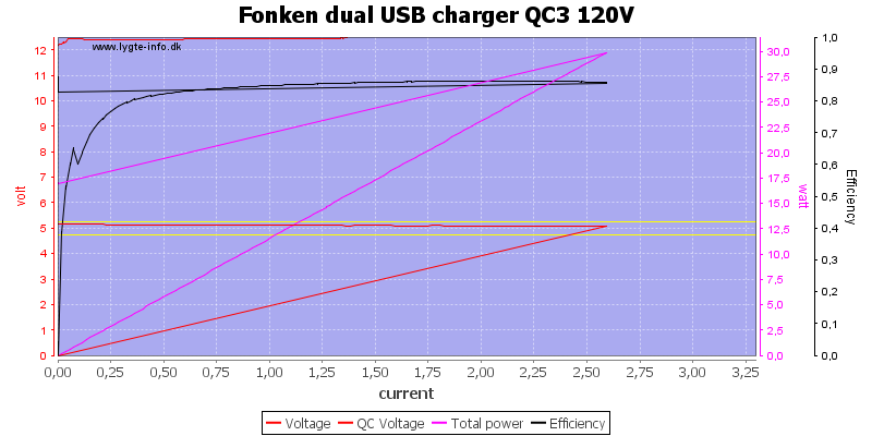
Also at 120VAC
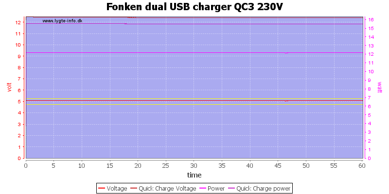
The charger could run for one hour at rated load.
The temperature photos below are taken between 30 minutes and 60 minutes into the one hour test.
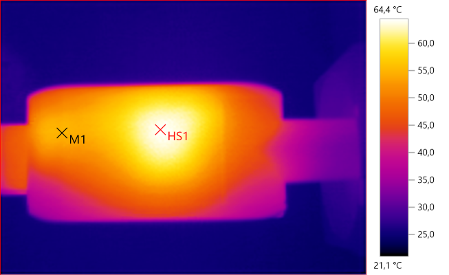
M1: 54.8°C, HS1: 64.4°C
HS1 is one of the transformers.
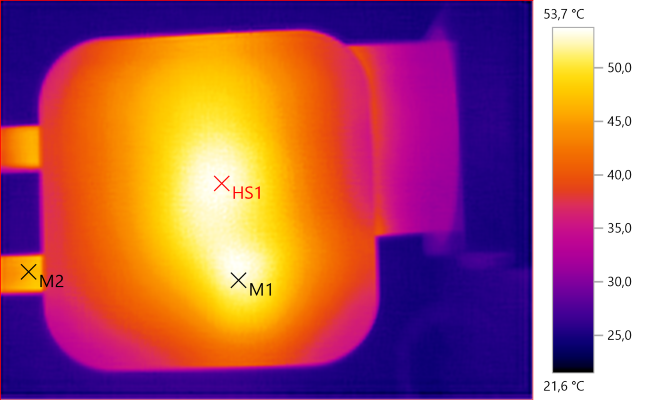
M1: 52.9°C, M2: 46.4°C, HS1: 53.7°C
M1 is the capacitor on top of a transformer, HS1 is the other capacitors transferring heat from the transformers to the enclosure.
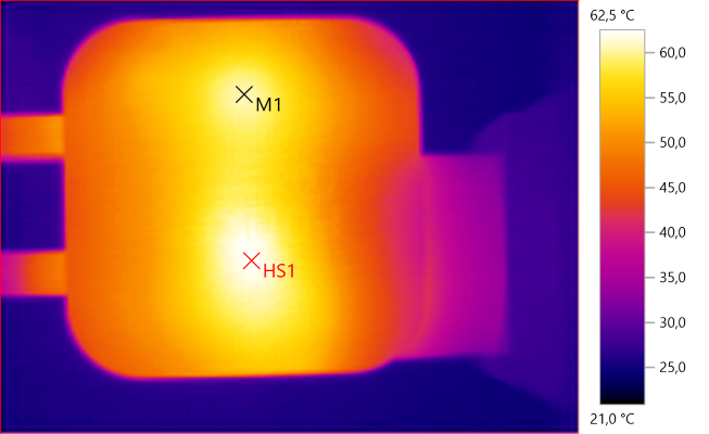
M1: 60.5°C, HS1: 62.5°C
HS1 is the switcher transistor for QC and M1 is for 5V.
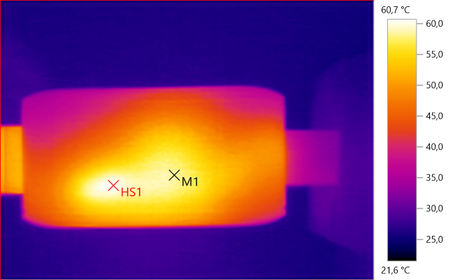
M1: 58.5°C, HS1: 60.7°C
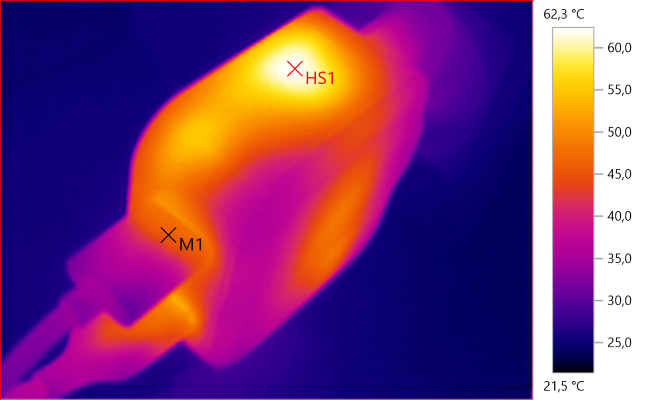
M1: 45.8°C, HS1: 62.3°C

At 0.5A the noise is 19mV rms and 709mVpp

At 1A the noise is 25mV rms and 758mVpp

At 2.5A the noise is 31mV rms and 700mVpp.
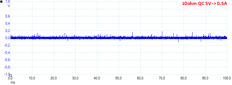
At 0.5A on the QC output the noise is 23V rms and 357mVpp.
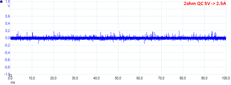
At 2.5A on the QC output the noise is 35mV rms and 437mVpp.
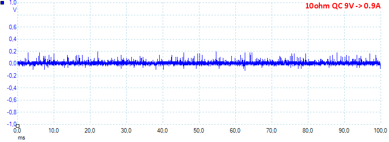
At 9V and 0.9A on the QC output the noise is 30mV rms and 375mVpp.
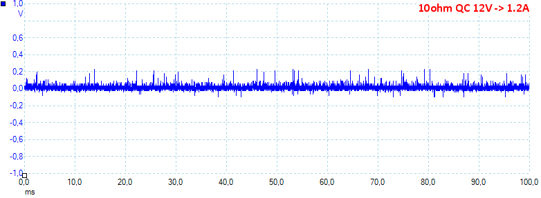
At 12V and 1.2A on the QC output the noise is 30mV rms and 428mVpp.
Tear down
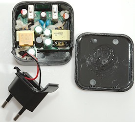
Pressing the sides a bit with my vice and I could break the lid off with a screwdriver, but I could not get the circuit board out before I had cut the other side off.
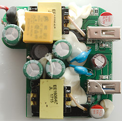
A fairly compact construction, with two transformers, but it have the low volt side very far away from the transformers. The input circuit is common. At the mains input is a fuse in black shrink wrap. Between the smoothing capacitors is a inductor (L1). There is a blue safety capacitor for each circuit. Each usb output has its own led (LED1 & LED2).
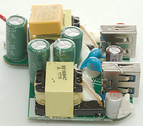
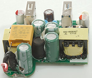
I was a bit hard on the circuit board and a capacitor while trying to get the circuit board out.
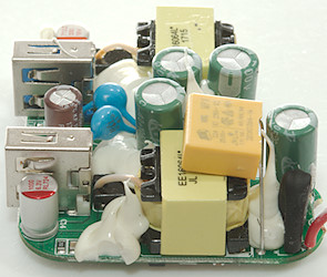
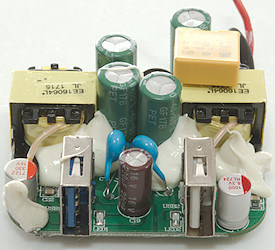
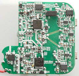
Most of the parts are on this side. At the mains input is the bridge rectifier (BD1), there are two switchers, one for the fixed 5V (U1: Marked 5K27) with a switcher transistor nearby (Q1: CS7N65, MOSFET 650V 7A). The other switcher is for the QC output, it used a 8 pin switcher controller (U2: Marked 1782-01/RA33H/UA1721), it uses a similar switcher transistor and due to the QC it need feedback from a opto-coupler (U3).
The 5V output has synchronous rectification (U4: Marked 4X0A, U5: marked 873-00/1628728/UB1621) and a auto coding chip (U8: UC2633). The QC output has a transistor for synchronous rectification (Q4: VS1018A 60V 18A 9mOhm) with a controller chip (U7: marked 6G3D) and a QC controller (U6: Marked 6AY0).
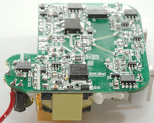
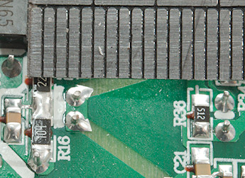
Safety distance looks good.
The charger passed the 2830 volt and the 4242 volt test.
Conclusion
With two port that can each deliver full power, auto coding on one port and QC on the other and no safety problems this looks like a good charger, even with the slightly high noise level.
Notes
Index of all tested USB power supplies/chargers
Read more about how I test USB power supplies/charger
How does a usb charger work?


